Directional Couplers are passive devices used for sampling incident and reflected microwave power, conveniently and accurately, with minimal disturbance to the transmission line. Directional couplers are used in many different testing applications where power or frequency needs to be monitored, leveled, alarmed or controlled. These include providing a signal sample for measurement or monitoring, feedback, combining feeds to and from antennas, antenna beam forming, providing taps for cable distributed systems such as cable TV, separating transmitted and received signals on telephone lines, in addition to electronic warfare (EW) systems and the emerging mmWave and 5G wireless communications systems. As coaxial systems reach higher frequencies, it becomes critical to sample and level signals over broad instantaneous bandwidths.
For many RF, microwave and mmWave systems, a constant monitoring of frequency is necessary from the output of microwave transmitters, systems or special test setups. A directional coupler is connected to the output of the system or instrument. A small amount of power and frequency is coupled from the main line and connected to a frequency meter. This provides a constant measurement of frequency. Power output from microwave transmitters may degrade as a function of time. A directional coupler may be used to couple a small amount of power from the main line. The power from the coupled port is then connected to a Power Meter where power can be constantly monitored. The power from the coupled port could be connected to a detector. The DC output voltage from the detector could be used in a feedback circuit to assure power output is constant – or – the voltage could be used to trigger shut down of the transmitter if the power is either too high or too low. The voltage could also be used to sound an alarm or trigger a data recorder as long as the power was out of its operating window. If the transmitter is located in a remote location, the voltage could cause an alert to be made to a technician that the transmitter is not performing to specifications.
Common properties desired for all directional couplers are wide operational bandwidth, high directivity, and a good impedance match at all ports when the other ports are terminated in matched loads. They couple a defined amount of the electromagnetic power in a transmission line to a port enabling the signal to be used in another circuit. An essential feature of directional couplers is that they only couple power flowing in one direction. Power entering the output port is coupled to the isolated port but not to the coupled port. A directional coupler designed to split power equally between two ports is called a hybrid coupler. In designing directional couplers for practical bandwidths, computer modeling and attention to design details help minimize causes of signal loss.
Four and Three Port Directional Couplers
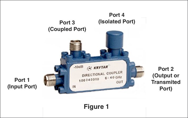
Directional couplers typically have four ports (Fig. 1). Port 1 is the Input Port where power is applied. Port 3 is the Coupled Port where a portion of the power applied to port 1 appears. Port 2 is the Output Port where the power from port 1 is outputted, less the portion that went to port 3. Directional couplers are frequently symmetrical so there also exists a Port 4, the Isolated Port. A portion of the power applied to port 2 will be coupled to port 4. However, the coupler is not typically used in this method and port 4 is terminated with a matched load (typically 50 ohms). This termination can be internal to the device and port 4 is not accessible. Effectively, this results in a 3-port coupler (Fig. 2).
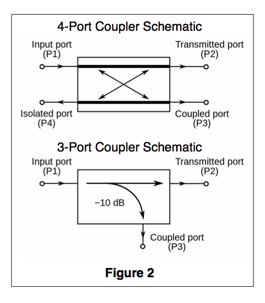
Three-port directional couplers are designed to generate two signal paths from an applied input signal. Directional couplers are often designed with a pair of adjacent transmission lines, such as microstrip or stripline transmission lines. In this architecture, one of the transmission lines is the main or through signal path with most of the power; the transmission line alongside it is the coupled line with one terminated port, often in a load resistor.
When microwave power is applied to the mainline circuit (Ports 1 and 2) a certain amount of energy will be “coupled” to the coupled circuit (port 3). In general, the closer the circuits are together, the more power will be applied to the coupled circuit from the main line circuit.
Ideally, the output-power level of the mainline signal would be reduced very little—only by the amount of signal power coupled from the input signal. However, normal insertion loss accounts for some additional loss of mainline power. The power level of the second output signal—the coupled signal path—is reduced by the coupling factor of the coupler along with any insertion loss associated with that signal path. Signal interfaces, such as coaxial connectors, will also contribute to some loss of initial signal power.
Designing Directional Couplers
Directional couplers are designed to operate within a well-matched system, such as 50 Ω, promoting smooth signal flow from a signal source, through the coupler’s input port, and through the output port to additional components in a system, such as a signal analyzer in a test system. Again, in real-life applications, some amount of impedance mismatch is inevitable, and signal power will be reflected at impedance mismatches. This results in an increase in return loss as signal power is sent back through the directional coupler, often dissipated as heat.
In designing directional couplers for practical bandwidths, computer modeling and attention to design details help minimize causes of signal loss. What makes the performance of any directional coupler unique is that it’s consistent across any specified bandwidth — not just in loss behavior, but in coupling, VSWR, and other critical parameters that gauge a directional coupler’s usefulness.
What Are Standard Directional Coupling Values?
Some standard values of coupling for KRYTAR directional couplers are 6 dB, 10 dB, 13 dB, 16 dB, 20 dB, 30 dB. Virtually any coupling value may be obtained through custom designs.
Q. What are directional couplers and how are they used?
A. Directional Couplers are passive devices used for sampling incident and reflected microwave power, conveniently and accurately, with minimal disturbance to the transmission line. Directional couplers are used in many different testing applications where power or frequency needs to be monitored, leveled, alarmed or controlled. These include providing a signal sample for measurement or monitoring, feedback, combining feeds to and from antennas, antenna beam forming, providing taps for cable distributed systems such as cable TV, separating transmitted and received signals on telephone lines, in addition to electronic warfare (EW) systems and the emerging mmWave and 5G wireless communications systems.
Q. What are common properties desired for a directional coupler?
A. Common properties desired for all directional couplers are wide operational bandwidth, high directivity, and a good impedance match at all ports when the other ports are terminated in matched loads.
Q. What is considered “Nominal Coupling”?
A. Nominal Coupling: The coupling factor, defined as dB, represents the primary property of a directional coupler. Coupling is not constant, but varies with frequency. While different designs may reduce the variance, a perfectly flat coupler theoretically cannot be built. Directional couplers are specified in terms of the coupling accuracy at the frequency band center.
Q. Aren’t all directional couplers created equal?
A. In designing directional couplers for practical bandwidths, computer modeling and attention to design details help minimize causes of signal loss. What makes the performance of any directional coupler unique is that it’s consistent across any specified bandwidth — not just in loss behavior, but in coupling, VSWR, and other critical parameters that gauge a directional coupler’s usefulness.
Q. Is it possible to obtain standard couplers without any painting on the case?
A. Yes, it is possible to obtain unpainted couplers leaving exposed metal surfaces.
In some cases applications may require maximum heat transfer from metal plate to ground. KRYTAR can supply couplers without any paint, or only one side unpainted, for direct surface grounding. The coupler will include silver epoxy around the case seams to prevent or minimize RF leakage.
Q. Do you have an environmental specification rating for directional couplers? And what about shock and vibration rating for directional couplers?
A. KRYTAR can take a look at a customer’s environmental rating requirements. In some cases, the unit can be mechanically enhanced in order to meet a customer’s required environmental specifications.
Military Standards (MIL-STD) testing (also called MIL-SPEC) is a body of test specifications approved for use by the United States Department of Defense (DOD). MIL-STD-810 is the most widely used specification and includes a nearly comprehensive collection of close to 30 environmental tests, including those related to temperature, solar radiation, sand and dust, acoustic noise, humidity, and vibration. Other MIL-STD tests include MIL-STD 202 for electronic and electrical component parts, MIL-STD 883 for microcircuits, and MIL-STD 1344 for electrical connectors. All KRYTAR directional couplers are tested per MIL-STD for shock and vibration.
Q. Looking at directional coupler specifications does the maximum insertion loss spec apply to both directions, S21 as well as S12?
A. A directional coupler is completely passive design. This design provides for a maximum insertion loss applies to both directions, S21 and S12.
Q. Directional coupler specifications show a power rating of 20W (avg) and 3kW (peak). Is it possible to use the pulse of 300W (peak) and 15% duty with a directional coupler? What about the pulse conditions (Pulse Width, Duty) of the peak power rating?
A. Directional couplers are designed to take a peak power of 3kW. Pulse width for these passive devices are not specified. It is highly recommend not to exceed 1-second duration at 300 Watts. By analysis a directional coupler may survive for more than 1 second. A demo unit could be supplied for this type of experiment
Q. Is there any information available about S parameters for directional couplers? How could someone obtain S parameter data?
A. KRYTAR can supply S parameter data for directional couplers upon request. The data can be saved and submitted as an S2P file or CSV file for further analysis.
Directional Coupler Definitions
Frequency Range (GHz): The frequency bandwidth in GHz over which a particular model will perform while meeting all its specification limits. KRYTAR directional coupler designs operate over the frequency area beginning at 0.5 GHz up to 110 GHz.
dB: A unit of gain equal to ten times the common logarithm of the ratio of two power levels or 20 times the common logarithm of the ratio between two voltages.
Nominal Coupling: The coupling factor, defined as dB, represents the primary property of a directional coupler. Coupling is not constant, but varies with frequency. While different designs may reduce the variance, a perfectly flat coupler theoretically cannot be built. Directional couplers are specified in terms of the coupling accuracy at the frequency band center.
Frequency Sensitivity: The maximum peak-to-peak variation in coupling (in dB) of a directional or hybrid coupler over the specified frequency range. Also referred to as “flatness”. KRYTAR directional couplers have frequency sensitivity tolerances of +/-0.3 dB for narrow band models to +/- 1.2 dB for broadband models.
Insertion Loss: The change in load power due to the insertion of a particular device into a transmission system. The main line insertion loss from port 1 to port 2 is due to some power going to the coupled port. The insertion loss consists of a combination of coupling loss, dielectric loss, conductor loss, and VSWR loss. Depending on the frequency range, coupling loss becomes less significant above 15 dB coupling where the other losses constitute the majority of the total loss. KRYTAR Insertion Loss includes coupled power. Dissipation in the circuit will raise the insertion loss by the power dissipation in dB.
Isolation: A unit of measure (in dB) that states the separation of signal levels on adjacent ports of a device. The greater the isolation value, less interference from a signal on one port is present at the other. Isolation of a directional coupler can be defined as the difference in signal levels in dB between the input port and the isolated port when the two other ports are terminated by matched loads. The isolation between the input and the isolated ports may be different from the isolation between the two output ports. For example, the isolation between ports 1 and 4 can be 30 dB while the isolation between ports 2 and 3 can be a different value such as 25 dB.
Directivity: A measurement of the desired signal strength to the undesired signal strength. Determined by taking the value of isolation and subtracting the specified coupling (including all variations). Directivity is a measure of how good the couplers performance is. Port 4 (Isolated Port) is not completely isolated in KRYTAR directional couplers as there are no perfect terminations. A small amount of power will be present at the isolated port. If power out of Port 4 (isolated port) is 20 dB below the power out of the coupled Port 3, the directional coupler directivity is 20 dB.
VSWR – (Voltage Standing Wave Ratio) or Return Loss: The ratio of the incident signal compared to the reflected signal in a transmission line. VSWR cannot be directly measured, so a return loss measurement (expressed in dB) is taken of reflected power to incident power. Once it is measured, it can be converted by equation to reflection coefficient which can be converted to VSWR. VSWR or Return Loss is caused by mismatches and discontinuities within the circuits of directional couplers. A mismatch on either port 1 (Input port) or port 4 (Terminated Port) will reduce directivity by an amount equal to return loss (in dB) of the mismatch. This permits measurement of Return Loss. Note that measurement of accurate Return Loss requires very high directivity (typically 30 to 40 dB).
Connectors: Standard 2.4mm Female connectors are used with optional 2.92 K Female connectors. SMA connectors are designed for use from DC to 26.5 GHz and are most commonly used in microwave systems. Higher frequencies call for 1.0mm or 1.85mm Female connectors.
KRYTAR specializes in the design and manufacturing of ultra-broadband, high-performance microwave components and test equipment. KRYTAR, founded by Thomas J. Russell in 1975, is a privately owned California corporation specializing in the manufacture of Ultra-Broadband mmWave, Microwave, and RF components and test equipment for both commercial and military applications. The KRYTAR product line includes directional couplers, directional detectors, 3 dB hybrids, MLDD power dividers, detectors, terminations, coaxial adapters and a power meter. Our products cover the DC to 110.0 GHz frequency range. The broadband design expertise at KRYTAR has created unique new designs, several of which are patented. KRYTAR has applied these designs to consistently introduce technologically advanced products with superior electrical performance and ruggedness.
Downloads
If you would like to download a PDF version of this page, you can do so by clicking here.