Generic selectors
Exact matches only
Search in title
Search in content
Post Type Selectors
post
page
product
Filter by Categories
Latest News
Upcoming Events

90 & 180 Degree Hybrid Coupler Primer

Hybrid Couplers are passive devices used to perform many functions, including splitting and combining signals in amplifiers, switching circuits, and antenna beam-forming networks used in a wide range of commercial and military applications where power or frequency needs to be monitored, leveled, alarmed or controlled.

Hybrid Couplers are passive devices used to perform many functions, including splitting and
combining signals in amplifiers, switching circuits, and antenna beam-forming networks used in a wide range of commercial and military
applications where power or frequency needs to be monitored, leveled, alarmed or controlled.

As the implementation of 5G and 5G NR (New Radio), SATCOM internet connectivity and direct to home (DTH) broadcast quickly gains
momentum, new high-performance devices, systems, and test and measurement equipment are needed to support the ultra-high
frequencies and high data rates that technologies like mmWave, multi-input multi-output (MIMO) antenna and RF front-end technology,
beam-forming and full duplex demand.

In the design, development, production and, test and measurement arenas, hybrid couplers are being used to split signals from tower-top
amplifiers to base station receivers, in applications to monitor system performance, to inject a signal into a system without interrupting its
service, in the creation of reflecting phase shifters, and much more.

Hybrid and directional couplers are 4-port passive devices based on the same operational principles but with different coupling levels
between ports. The two devices are used for different purposes. Hybrids are a special kind of a four-port directional coupler used to split
or combine signals with specific phase relations, while directional couplers (i.e., hybrids with coupling coefficient different from -3 dB) are
used to sample forward and/or reflected waves propagating along a line. Understanding the nature of the signals being combined is the
key to defining the best configuration for your application. Hybrids are available in many phase and amplitude variations.

Hybrids Come in Two Types: 90 and 180 Degree

90-Degree or Quadrature Hybrids

The 3 dB, 90-degree hybrids are often know as quadrature hybrids because a signal applied to any input, will result in two equal
amplitude signals that are both quadrant (90 degrees separated from one another). The signals at the outputs are attenuated by three
decibels (3 dB) and have a 90 degree phase difference with respect to each other. The 3 dB attenuation means that only 50% of the input
power will appear at one of the outputs since the other 50% is flowed down to the other output leg. It also makes no difference which
port is the input because the relationship at the outputs remains the same as these devices are electrically and mechanically symmetrical.
Reflections due to mismatches are sent to the isolation port preventing any power from reflecting back to the input port. In addition to
splitting a signal they can also be used to combine power signals with a high degree of isolation between the ports. This configuration
ensures a high degree of isolation between the two output ports and the two input ports without unwanted interaction between them
(Figure 1).

90-degree hybrids from KRYTAR use a three-layer stripline construction (Figures 2 & 3). Coupled lines are etched on opposite sides of a
thin copper board sandwiched between two equally thick dielectric boards.

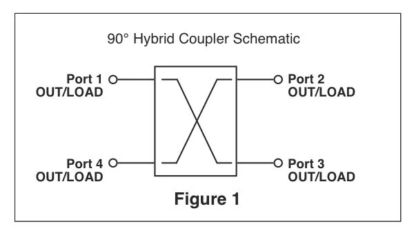
Typically, 90-degree hybrids are used in circuits requiring a balanced division of power into two transmission lines with 90° separation of
phase. Applications include signal splitters, combiners, balanced mixers, image-rejection mixers, phase shifters, diplexers, switches and
antenna feed networks. The increasing use of broadband microwave systems, and the emerging mmWave and 5G wireless
communications systems, has created a need for broadband 90° hybrids with tight output amplitude and phase tracking.

180-degree Hybrids
The 180-degree hybrids (also referred to as the “rat race” couplers) are four-part devices that are utilized to either equally divide an input signal or to add-up two fused signals. An extra benefit of this hybrid coupler is to alternately offer an equally-divided 180 degree phase-shifted output signals.

Broadband hybrids have traditionally been developed in 90° configurations with less bandwidth generally available for the greater phase relationship of a 180° hybrids. Systems such as antenna beamforming networks can be designed more efficiently with 180° hybrids since less components are required to recombine divided signals.

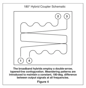
Hybrids are four-port components with dual input and output ports (Figures 4 & 5). A signal applied to the sum (∑) input port produces two output signals of matched amplitude and phase. In 3-dB hybrids each output level is 3-dB lower (less the insertion loss through the hybrid) than the input level. Signals applied to the difference (∆) input port produces two equal-amplitude output signals that are 180° out of phase with each other. The characteristic makes such hybrid circuits ideal for reducing noise in amplifiers via feedback combining techniques or for merging multiple signals from arrays.

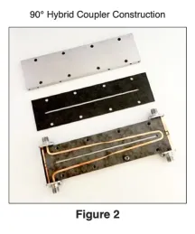
KRTYAR 180° hybrids are designed with a double-arrow construction technique in which two stripline, asymmetric, tapered-line directional couplers are cascaded. Meandering transmission lines on each side of the hybrid maintain the even180-degree phase relationship between channels at all frequencies. 
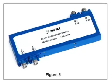
Fabrication of the double-arrow hybrids requires asymmetric coupler with completely overlapped lines at its coupled end (where the lines cross) that form an instantaneous transmission from high coupling to no coupling. The hybrids are constructed with a three-layer stripline configuration. Coupled lines are etched on opposite sides of a thin coupler circuit board, sandwiched between a pair of equal-thickness dielectric boards.

The double-arrow configuration overcomes many of the bandwidth restrictions that have limited the use of 180-degree hybrids in the past. This development allows a typical electronic warfare (EW),or commercial antenna beam-forming network to be housed in a single, compact enclosure (Figure 6). The180° hybrid devices come with SMA connectors, although other connector types are available for higher frequency applications.

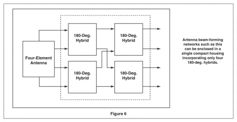
Delay Output Signals with a Hybrid Coupler
Depending on the application, some engineers ma want to delay an output signal by a certain time. Both 90 and 180-degree hybrids can accomplish this. However, in a 90-degree hybrid, the delay would mean that the signal on one of the output ports would lag the other by 1/4 of the period. In terms of time, 1/4 of a period would depend on the frequency. In a 180-degree hybrid, the lag or delay is 1/2 or halfway through the period. So an engineer would use a 180-degree hybrid if more lag is desired compared to a 90-degree hybrid.

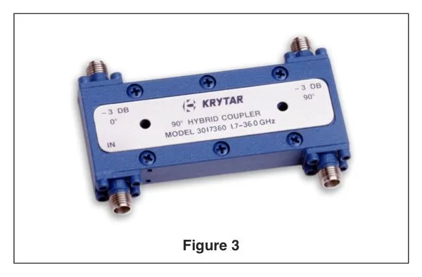
KRYTAR’s Hybrid Couplers offer wide frequency coverage in single, compact packages which provide low insertion loss, high directivity and tight coupling. These hybrid couplers offer simple solutions in many applications within those frequency bands including electronic warfare (EW), commercial wireless, SATCOM, radar, signal monitoring and measurement, antenna beam-forming, and EMC testing environments. For many space-restricted situations the compact size of these KRYTAR couplers are ideal. These couplers can be also be manufactured to meet military specifications.

Standard Coupling Values
Some standard values of coupling for KRYTAR directional couplers include 6 dB, 10 dB, 13 dB, 16 dB, 20 dB, and 30 dB. KRYTAR offers complete engineering services for custom designs that meet or exceed critical performance and/or packaging specifications. Virtually any coupling value may be obtained through custom designs.

Hybrid Couplers FAQs

Q. What are hybrid couplers and ho ware they used?
A. Hybrid Couplers are passive devices used to perform many functions, including splitting and combining signals in amplifiers, switching circuits, and antenna beam-forming networks used in a wide range of commercial and military applications where power or frequency needs to be monitored, leveled, alarmed or controlled.

Q. Why use a hybrid coupler vs a directional coupler?
A. Hybrid and directional couplers are 4-port passive devices based on the same
operational principles but with different coupling levels between ports. The two devices are used for different purposes. Hybrids are a special kind of a four-port directional coupler used to split or combine signals with specific phase relations, while directional couplers (i.e., hybrids with coupling coefficient different from -3 dB) are used to sample forward and/or reflected waves propagating along a line. Understanding the nature of the signals being combined is the key to defining the best
configuration for your application. Hybrids are available in many phase and
amplitude variations.

Q. Are there different types of hybrid couplers?
A.
Hybrids Come in Two Types: 90 and 180 Degree. 90-Degree are often know as quadrature hybrids because a signal applied to any input, will result in two equal amplitude signals that are both
quadrant (90 degrees separated from
one another). The 180-degree hybrids (also referred to as the “rat race” couplers) are four-part devices that are

utilized to either equally divide an input signal or to add-up two fused signals. An extra benefit of this hybrid coupler is to alternately offer an equally-divided 180 degree phase-shifted output signals.

Q. How do I select a hybrid coupler?
A. When selecting a hybrid coupler it is important to know the parameters that you are looking for. Some key parameters would be: Phase Shift Type (90 or 180-degree), Operating Frequency (GHz, Min. and Max.), Insertion Loss (dB, Max.), and Isolation (dB, Min.).

Start by reviewing KRYTAR’s hybrid couplers Web page:

See the product page for 90 or 180 degree couplers. Begin by sorting the KRYTAR 90 and 180-degree couplers by either minimum frequency or maximum frequency (low to high GHz, or high to low GHz). Additional parameters will be
displayed to make your selection easy.

Q. I can’t find a hybrid coupler to meet my specific requirements. Can KRYTAR help me in my quest?
A. Absolutely! KRYTAR engineers are available to discuss your requirements
and come up with a solution. KRYTAR is well known in the industry for custom designs and solutions for the most
demanding requirements. Chances are we’ve already solved it. So give us a call,
send an email or contact us using the online form:

Q. Can standard SMA connectors be used in an ultrawideband application?
A. SMA connectors are designed for applications operating from DC to 35
GHz (Extendable up to 40 GHz). For best results, you’ll need a hybrid coupler that comes with 2.92 mm, or “K Type” connectors. The K connector is designed for use up to 40 GHz. KRYTAR
hybrid coupler models that come with these are identified by the letter “K” at the end of the model number. If you need other types of connectors, just let us know.

Q. I need a hybrid for a thermal vacuum application. Can you help?
A. Yes! KRYTAR has a number of components designed for both commercial and military thermal vacuum and space applications. We have a 180-
degree Hybrid operating within 0.5 to 26.5 GHz for thermal vac applications
and a 180-degree hybrid operating 1.0 to 26.5 GHz for space applications. KRYTAR can provide customized solutions to meet your application-specific requirements, just let us know. See our Space Applications page for additional products:

Hybrid Coupler Definitions

Frequency Range (GHz): The frequency bandwidth in GHz over which a particular model will perform while meeting all its specification limits. KRYTAR directional coupler designs operate
over the frequency area beginning at 0.5 GHz up to 110 GHz.

dB: A unit of gain equal to ten times the common logarithm of the ratio of two power levels or 20 times the common logarithm of the ratio between two voltages.

Nominal Coupling: The coupling factor, defined as dB, represents the primary property of a directional coupler. Coupling is not constant, but varies with frequency. While different designs may reduce the variance, a perfectly flat coupler theoretically cannot be built. Directional couplers are specified in terms of the coupling accuracy at the frequency band center.

Frequency Response: The ability of a device (such as an audio amplifier) to handle the frequencies applied to it. A frequency response function is a mathematical representation of the relationship between the input and the output of a system. It is a measure of magnitude and phase of the output as a function of frequency, in comparison to the input.

Insertion Loss: The change in load power due to the insertion of a particular device into a transmission system. The main line insertion loss from port 1 to port 2 is due to some power going to the coupled port. The insertion loss consists of a combination of coupling loss, dielectric loss, conductor loss, and VSWR loss. Depending on the frequency range, coupling loss becomes less significant above 15 dB coupling where the other losses constitute the majority of the total loss. KRYTAR Insertion Loss includes coupled power. Dissipation in the circuit will raise the insertion loss by the power dissipation in dB.

Isolation: A unit of measure (in dB) that states the separation of signal levels on adjacent ports of a device. The greater the isolation value, less interference from a signal on one port is present at the other. Isolation of a directional coupler can be defined as the difference in signal levels in dB between the input port and the isolated port when the two other ports are terminated by matched loads. The isolation between the input and the isolated ports may be different from the isolation between the two output ports. For example, the isolation between ports 1 and 4 can be 30 dB while the isolation between ports 2 and 3 can be a different value such as 25 dB.

Directivity: A measurement of the desired signal strength to the undesired signal strength. Determined by taking the value of isolation and subtracting the specified coupling (including all
variations). Directivity is a measure of how good the couplers performance is. Port 4 (Isolated Port) is not completely isolated in KRYTAR directional couplers as there are no perfect terminations. A small amount of power will be present at the
isolated port. If power out of Port 4 (isolated port) is 20 dB
below the power out of the coupled Port 3, the directional
coupler directivity is 20 dB.

VSWR – (Voltage Standing Wave Ratio) or Return Loss: The ratio of the incident signal compared to the reflected signal in a transmission line. VSWR cannot be directly measured, so a return loss measurement (expressed in dB) is taken of reflected
power to incident power. Once it is measured, it can be
converted by equation to reflection coefficient which can be converted to VSWR. VSWR or Return Loss is caused by
mismatches and discontinuities within the circuits of directional couplers. A mismatch on either port 1 (Input port) or port 4
(Terminated Port) will reduce directivity by an amount equal to return loss (in dB) of the mismatch. This permits measurement of Return Loss. Note that measurement of accurate Return Loss
requires very high directivity (typically 30 to 40 dB).

Connectors: Standard 2.4mm Female connectors are used with optional 2.92 K Female connectors. SMA connectors are designed for use from DC to 26.5 GHz and are most commonly used in microwave systems. Higher frequencies call for 1.0mm or 1.85mm Female connectors.

Solutions from KRYTAR
KRYTAR specializes in the design and manufacturing of ultra-broadband, high-performance microwave components and test equipment. KRYTAR, founded by Thomas J. Russell in 1975, is a privately owned California corporation specializing in the
manufacture of Ultra-Broadband mmWave, Microwave, and RF
components and test equipment for both commercial and
military applications. The KRYTAR product line includes
directional couplers, directional detectors, 3 dB hybrids, MLDD power dividers, detectors, terminations, coaxial adapters and a power meter. Our products cover the DC to 110.0 GHz frequency range. The broadband design expertise at KRYTAR has created unique new designs, several of which are patented. KRYTAR has applied these designs to consistently introduce
technologically advanced products with superior electrical performance and ruggedness.

# # #

KRYTAR Ultra-Broadband Microwave Components and Test Equipment DC-67 GHz

This product has been added to your RFQ list.