Generic selectors
Exact matches only
Search in title
Search in content
Post Type Selectors
post
page
product
Filter by Categories
Latest News
Upcoming Events

Power Dividers are passive devices used to perform many functions, including splitting or combining signals in amplifiers, switching circuits, and antenna beamforming networks used in a wide range of commercial and military applications where power or frequency needs to be monitored, leveled, alarmed or controlled. RF and microwave systems may require power to be divided between two or more applications. In these cases, a device to facilitate the division of an input power is required.

Important specifications when determining how to use a power divider includes insertion loss, amplitude and phase balance and return losses. For power combining of uncorrelated signals, the most important specification is the isolation, which is the insertion loss from one equal power port to the other.

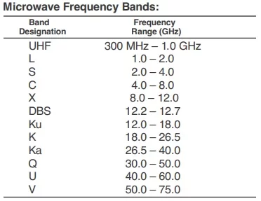
As the implementation of 5G and5G NR (New Radio), Wi-Fi 6 and Wi-Fi 6E wireless local-area network (WLAN) protocol, SATCOM internet connectivity and direct to home (DTH) broadcast continues to gain momentum, new high-performance devices, systems, and test and measurement equipment are needed to support the ultra-high frequencies and high data rates that technologies like mmWave, multi-input multi-output (MIMO) antenna and RF frontend technology, beamforming and full duplex demand.
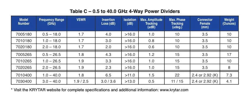
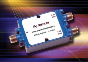
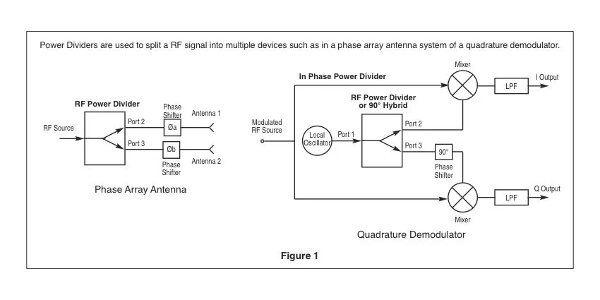
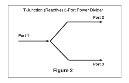
The power divider splits an input signal into two or more outputs that are usually, but not always, equal in amplitude and phase. Power dividers are available in a number of configurations including 2-way, 4-way and 8-way. Regardless of its type, the goal of every power divider is to have the greatest port-to-port isolation, lowest insertion loss and voltage standing wave ratio (VSWR), and least amplitude and phase imbalance over the entire frequency range of the device. Some examples where power dividers are in use include splitting a RF signal into multiple devices such as in a phase array antenna system of a quadrature demodulator (Figure 1).

The first example is a phased array antenna where the RF source is split between the two antenna elements. Typically antennas of this type have two to eight or more elements, each of which is driven from a power divider output port. Phase shifters are generally external to the divider to allow for electronic control to steer the antenna’s field pattern.

The second example is a quadrature demodulator that requires a local oscillator be delivered to two mixers that demodulate the RF source into the inphase (I) and quadrature (Q) modulation  components. The 90° phase shift required to demodulate the Q signal can be external as shown or can be internal to the power divider. In both cases the signal power levels are equal.

The power divider can be run “backwards” so that multiple inputs can be combined into a single output making it a power combiner. In combiner mode these devices are capable of performing vector addition or subtraction of signals based on their amplitude and phase values. 

There are a number of types of power divider designs available in the industry including the two most common: T-Junction (Reactive) and Wilkinson.

The T-Junction (Reactive) Power Divider 

The earliest power dividers, which were T-junctions, had no isolation between output ports. In Figure 2 (A simple T-junction) power is input through Port 1 and is supposed to be divided evenly between Port 2 and Port 3 without reflection. However, due to the poor isolation, power directed toward P2 could be reflected to P3 if the ports are not matched, making the power output through Port 2 and Port 3 uneven and potentially damaging a part of the system. It is possible to use this design with four ports where power arriving at Port 2 is split between Port 1 and
Port 4 (which is terminated with a matching load) and none will go to Port 3 (in an ideal case). These types of power dividers have limited capabilities in high frequency RF and microwave systems.

The Wilkinson Power Divider 

The Wilkinson power splitter was invented around 1960 by an engineer named Ernest Wilkinson. 

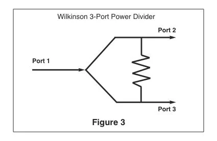
As isolation is the most important parameter for a power divider, if there is an impedance mismatch or other issue at an output port, high isolation prevents the other port(s) from being affected. A Wilkinson power divider splits an input signal into two equal phase output signals, or combines two equal-phase signals into one in the opposite direction.A Wilkinson divider relies on quarter-wave transformers to match the split port. A resistor is placed across the outputs, Figure 3, where it does no harm to the input signal at Port 1. This greatly improves isolation and allows all ports to be impedance matched.


The Wilkinson design solves the matching problems of the simple T-Junction as it has low VSWR at all ports and high isolation between output ports. This type of divider is often used in multi-channel radio frequency systems because it can provide a high degree of isolation between the output ports. By cascading more quarter wave sections, Wilkinson power dividers can easily handle 9:1 bandwidths of many electronic warfare and communications systems. 
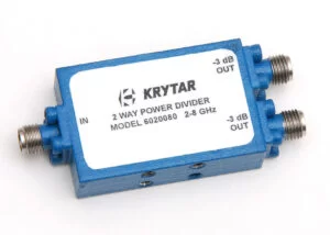
An example of  a KRYTAR Wilkinson design 2-way power divider is Model 6020080 with a frequency range of 2.0- 8.0 GHz (S and CBands). This power divider offers Isolation of >19.5 dB, Insertion Loss of <0.8 dB and Amplitude Tracking of ±0.25 dB. The Matched-Line Directional Divider (MLDD) 
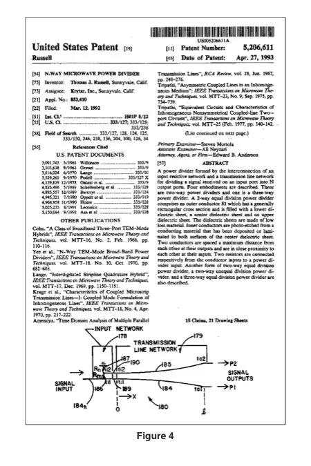
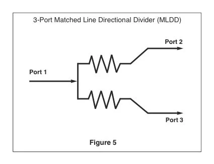
In 1993 Thomas J. Russell developed and received United States Patent #5,206,611, (Figure 4) for his concept of the matched-line directional divider (MLDD) designed to provide effective operation over very wide bandwidths. The reactive power divider has limited capabilities when attempting to be used in high frequency applications. A Wilkinson type of power divider is best for narrow bandwidth applications because it’s design uses quarter wavelength sections. The MLDD design power divider overcomes many of these limitations. (Figure 5). 
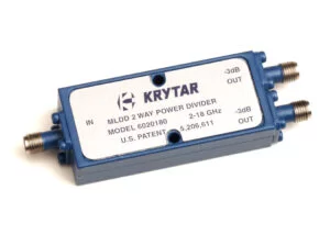
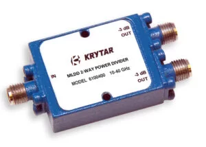
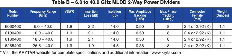
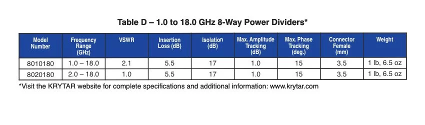
The MLDD’s design uses tapered transmission lines which results in having a high pass frequency response. With exceptional performance over a ultrabroadband frequency range the MLDD designed power divider offer excellent solutions for many of  today’s test and measurement application requirements. KRYTAR has used its proprietary patented design to produce a wide assortment of MLDD power dividers with exceptional performance over a ultra-broadband frequency range. KRYTAR MLDD 2-way power dividers are a unique class of directional devices.

Some examples of KRYTAR MLDD 2-way power dividers with frequency ranges from 0.5 to 18.0 GHz (UHF thru Ku-Bands) include: Model 6005180, 0.5- 18.0 GHz; Model 6010180, 1.0-18.0 GHz; Model 6020180, 2.0-18.0 GHz (Table A and Figure 6).

Where higher frequency requirements are needed KRYTAR MLDD 2-way power divider models offer excellent performance over the ultra-broadband frequency range of 6.0 to 40.0 GHz (C thru Ka-Bands) in single, compact, packages. Examples include: Models 6060400, 6-40 GHz; Model 6100400, 10-40 GHz; Model 6180400, 18-40 GHz; Model 6265400, 26.5-40.0 GHz. (Table B) These power dividers come with standard female 2.4-mm connectors and are available with 2.92mm (K) connectors that operate mode-free up to 40 GHz.

4- and 8-Way Power Dividers
For those situations where designs require more
outputs, KRYTAR produces a number of MLDD 4-
way power dividers covering the frequency ranges
of 0.5 – 18 GHz (L thru Ku-Bands), 0.5 – 26.5 GHz
(UHF thru K-Bands) and 1.0 – 40.0 GHz (L thru KaBands) (Table C). In addition, the company offers 8-
way power dividers covering the frequency ranges
of 1.0 – 18 GHz (L thru Ku-Bands) (Table D).

The theoretical Insertion Loss of a KRYTAR Power Divider with 2 output ports is 3 dB, with 4 output ports is 6 dB, and with 8 outports is 9 dB. KRYTAR Powder Divider Insertion Loss does not include the theoretical split loss and consist of the power dissipated by the input network and material losses.

Power dividers are often used in multi-channel RF and microwave systems and other telecommunications electronic defense systems that may require dividing power equally. Using the right power divider can provide the solution to many difficult design challenges.

Power Divider Specification & Definitions

Frequency Sensitivity is the amount of frequency change in the carrier frequency per unit amplitude change in the message signal.

mmWave (mm-Wave): 

Millimeter wave is the band of spectrum between 30 GHz and 300 GHz. Wedged between microwave and infrared waves, this spectrum can be used for high-speed wireless communications as seen with the latest 802.11ad Wi-Fi standard (operating at 60 GHz). It is being considered by standards organizations, the Federal Communications Commission and researchers as the way to bring “5G” into the future by allocating more bandwidth to deliver faster, higher-quality video, and multimedia content and services.

Insertion Loss 

In telecommunications whenever a signal travels through a component or a system, there is always some loss of power due to a number of reasons. The loss that occurs while a signal is traveling through a component or system is called as Insertion Loss. It is usually expressed in decibels (dB)

5G: 

The fifth generation (5G) of cellular service, superseding 4G LTE. Governed by the 3GPP, 5G will increase transmission speed dramatically and embrace prioritization.As wireless data increases exponentially, real-time content such as video calling and video streaming must be given a higher priority than data on Web pages.

5G NR (5G New Radio) 

The 5G new radio access technology (RAT) air-interface is a global standard, which like 4G also uses OFDM modulation, and is designed to deliver data rates up to 20 Gbps, enabling individual users to get gigabit-per-second downloads over the air (OTA). Wireless virtual reality (VR) and augmented reality (AR) can become commonplace, and 5G is expected to provide a huge boost for connecting billions of Internet of Things (IoT) devices.

VSWR is defined as the ratio of the maximum voltage
to the minimum voltage in standing wave pattern
along the length of a transmission line structure. It
varies from 1 to (plus) infinity and is always positive.

Amplitude and Phase Tracking are the ratio of one
output to the other in dB or degrees respectively.

Wi-Fi 6: 

Wi-Fi 6 is the most recent iteration of the IEEE standard for wireless local-area network (WLAN) protocol and is a substantial upgrade over its predecessors Wi-Fi 4 and Wi-Fi 5. Wi-Fi 6 operates between 2.4 GHz and 5 GHz. Wi-Fi 6 can be significantly faster due to technologies like traffic prioritization, OFDMA, and beamforming.

Wi-Fi 6E :

Wi-Fi 6E operates at 6 GHz (5.925–7.125 GHz in the U.S.) and also the 2.4 GHz or 5 GHz devices already in use. Wi-Fi 6E-enabled devices can take advantage of the newer 6 GHz frequency band
for further improved connectivity.

Frequency Range (GHz): 

The frequency bandwidth in GHz over which a particular model will perform while meeting all its specification limits. KRYTAR directional coupler designs operate over the frequency area beginning at 0.5 GHz up to 110 GHz.

dB: 

A unit of gain equal to ten times the common logarithm of the ratio of two power levels or 20 times the common logarithm of the ratio between two voltages. 

Frequency Response:

The ability of a device (such as an audio amplifier) to handle the frequencies applied to it. A frequency response function is a mathematical representation of the relationship between the input and the output of a system. It is a measure of magnitude and phase of the output as a function of frequency, in comparison to the input.

Insertion Loss: 

The change in load power due to the insertion of a particular device into a transmission system. The main line insertion loss from port 1 to port 2 is due to some power going to the coupled  port. The insertion loss consists of a combination of coupling loss, dielectric loss, conductor loss, and VSWR loss. Depending on the frequency range, coupling loss becomes less significant above 15 dB coupling where the other losses constitute the majority of the total loss. KRYTAR Insertion Loss includes coupled power. Dissipation in the circuit will raise the insertion loss by the power dissipation in dB.

Isolation: 

A unit of measure (in dB) that states the
separation of signal levels on adjacent ports of a
device. The greater the isolation value, less interference
from a signal on one port is present at the other. Isolation of a power divider can be defined as the difference in signal levels in dB between two output ports
when the other ports are terminated by matched
loads such as KRYTAR’s 50 Ohm termination, model
T3M.

VSWR – (Voltage Standing Wave Ratio) or Return Loss:

The ratio of the incident signal compared to the reflected signal in a transmission line. VSWR cannot be directly measured, so a return loss measurement (expressed in dB) is taken of reflected power to incident power. Once it is measured, it can be converted by equation to reflection coefficient which can be converted to VSWR. VSWR or Return Loss is caused by mismatches and discontinuities within the circuits of directional couplers. A mismatch on either port 1 (Input port) or port 4 (Terminated Port) will reduce directivity by an amount equal to return loss (in dB) of the mismatch. This permits measurement of Return Loss. Note that measurement of accurate Return Loss requires very high directivity (typically 30 to 40 dB).

Connectors:

Standard 2.4mm Female connectors are used with optional 2.92 K Female connectors. SMA connectors are designed for use from DC to 26.5 GHz and are most commonly used in microwave systems. Higher frequencies call for 1.0mm or 1.85mm Female connectors.

KRYTAR specializes in the design and manufacturing of ultra-broadband, high-performance microwave components and test equipment. KRYTAR, founded by Thomas J. Russell in 1975, is a privately owned California corporation specializing in the manufacture of Ultra-Broadband mmWave, Microwave, and RF components and test equipment for both commercial and military applications. The KRYTAR product line includes directional couplers, directional detectors, 3 dB hybrids, MLDD power dividers, detectors, terminations, coaxial adapters and a power meter. Our products cover the DC to 110.0 GHz frequency range. The broadband design expertise at KRYTAR has created unique new designs, several of which are patented. KRYTAR has applied these designs to consistently introduce technologically advanced products with superior electrical performance and ruggedness.

KRYTAR Ultra-Broadband Microwave Components and Test Equipment DC-67 GHz

This product has been added to your RFQ list.