This article was originally published in a Microwave RF Journal article, September 1985.
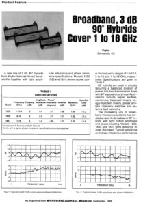
A new line of 3 dB, 90° hybrids from KRYTAR features broadband- widths together with tight amplitude imbalance and phase imbalance specifications. Models 1230, 1830 and 1831, shown above, cover the frequency ranges of 1 to 12.4, 2 to 18 and 1 to 18 GHz, respectively. Specifications are given in Table 1.
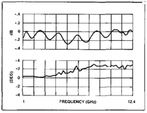
Fig. 1 Typical model 1230 amplitude and phase imbalance.
90° hybrids are used in circuits requiring a balanced division of power into two transmission lines with 90° separation of phase. Applications include signal splitters, combiners, balanced mixers, image-rejection mixers, phase shifters, diplexers, switches and antenna feed networks.
The increasing use of broadband microwave systems has created a need for broadband 90° hybrids with tight output amplitude and phase tracking. Models 1230, 1830 and 1831 were designed to meet this need. Typical amplitude and phase imbalance performance.
For these units is shown in Figures 1 and 2. These curves are of the 90° out port with respect to the 0° out port. The data were taken with a Hewlett-Packard model 8510 automatic network analyzer.
| Model | Frequency (GHz) | Coupling (dB) | Amplitude Imbalance (dB) | Phase* Imbalance (degrees) | Isolation (dB) | Maximum SWR | Insertion Loss (dB) |
| 1230 | 1 – 12.4 | 3 | ±.4 | ±7 | > 20 | 1.30 | < 1.3 |
| 1830 | 2 – 18 | 3 | ±.4 | ±7 | > 17 | 1.35 | < 1.4 |
| 1831 | 1 – 18 | 3 | ±.5 | ± 10 | > 17 | 1.35 | < 1.8 |
Connectors: N Female or SMA Female
* Units with a tighter phase imbalance specifications can be supplied
All three models use a three-layer stripline construction. Coupled lines are etched on opposite sides of a thin coupler board sandwiched between two equal thickness dielectric boards. Rogers 5870 duroid is used throughout.
Figure 3 shows a model 1230 with cover and top dielectric board removed. The tight 3 dB coupling of each hybrid is achieved by using the technique of connecting two symmetrical 8.34 dB directional couplers in tandem.[1]
Figure 4 is a sketch of the coupler board showing top and bottom conductors. The identical 8.34 dB couplers are realized using a nonuniform tapered line design synthesized with a CAD program developed at KRYTAR.
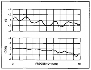
Fig.2 Typical model 1830 amplitude and phase imbalance |
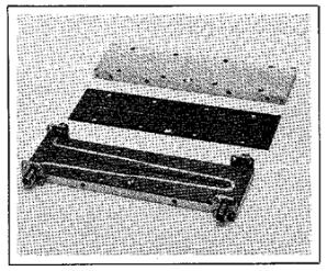
Fig. 3 Model 1230 with cover and top dielectric board removed. |
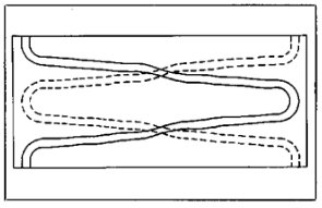
Fig 4. Coupler board conductor pattern. |
[1] Monteath, G.D., “Coupled Transmission Lines as Symmetrical Directional Couplers,” Proc. IEE, Part B, Radio and Electronic Eng., Vol. 102, No. 3, May 1955, pp. 383-392.
Couplers,” Proc. IEE, Part B, Radio and Electronic Eng., Vol. 102, No. 3, May 1955, pp. 383-392.