End Launch Terminations
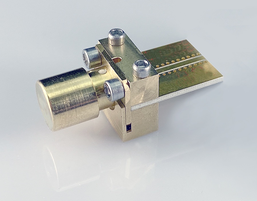
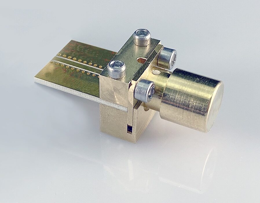
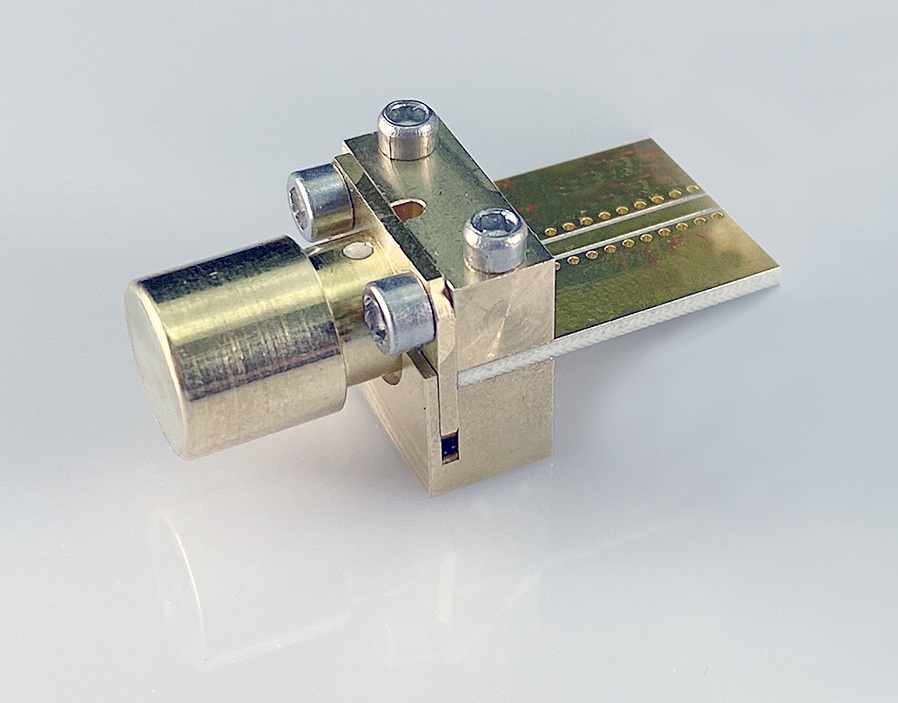
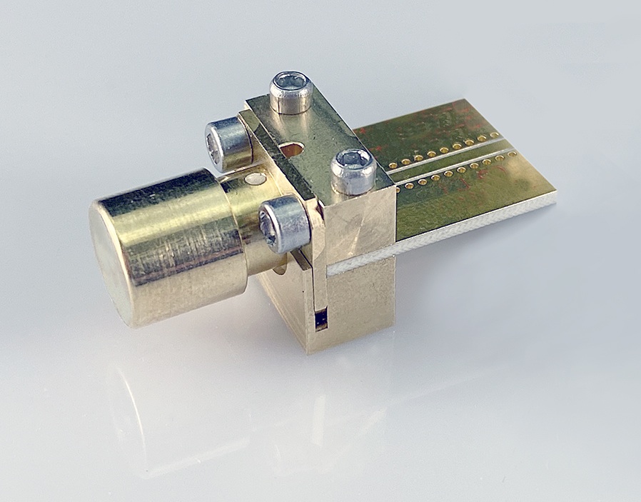
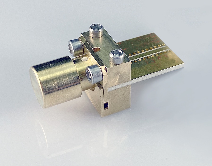
KRYTAR has developed a line of End Launch Terminations featuring a unique, patent-pending, integrated termination eliminating the additional cost and complexity of typical coaxial terminations. With the termination already integrated, these complete End Launch packages offer a simple solution for reducing the time-consuming task required to install separate coaxial terminations.
FEATURES
DC to 50 GHz
Power Rating: 0.5 Watt
Low VSWR
Superior Electrical Performance
Fully 50 Ohm Matched Assembly
Operating Temperature: -65 to +125°C
| Product Image | Model Number | Freq.Min | Freq.Max (GHz) | Launch Pin Diameter (Inch) | Substrate Thickness (Inch) | Height (Y) Max. (Inch) | VSWR | Impedance (Ohm) | Data Sheet/Outline Drawings | Add To RFQ |
|---|---|---|---|---|---|---|---|---|---|---|
| DC | 50 | 0.01 | 0.2 - 0.3 | 0.77 | 1.5:1 | 50 ±1 | ||||
| DC | 50 | 0.01 | 0.1 - 0.2 | 0.69 | 1.5:1 | 50 ±1 | ||||
| DC | 50 | 0.01 | 0.005 - 0.1 | 0.60 | 1.5:1 | 50 ±1 | ||||
| DC | 50 | 0.007 | 0.2 - 0.3 | 0.77 | 1.5:1 | 50 ±1 | ||||
| DC | 50 | 0.007 | 0.1 - 0.2 | 0.69 | 1.5:1 | 50 ±1 | ||||
| DC | 50 | 0.007 | 0.005 - 0.1 | 0.60 | 1.5:1 | 50 ±1 | ||||
| DC | 50 | 0.005 | 0.2 - 0.3 | 0.77 | 1.5:1 | 50 ±1 | ||||
| DC | 50 | 0.005 | 0.1 - 0.2 | 0.69 | 1.5:1 | 50 ±1 | ||||
| DC | 50 | 0.005 | 0.005 - 0.1 | 0.60 | 1.5:1 | 50 ±1 | ||||
| DC | 40 | 0.01 | 0.2 - 0.3 | 0.77 | 1.4:1 | 50 ±1 | ||||
| DC | 40 | 0.01 | 0.1 - 0.2 | 0.69 | 1.4:1 | 50 ±1 | ||||
| DC | 40 | 0.01 | 0.005 - 0.1 | 0.60 | 1.4:1 | 50 ±1 | ||||
| DC | 40 | 0.007 | 0.2 - 0.3 | 0.77 | 1.4:1 | 50 ±1 | ||||
| DC | 40 | 0.007 | 0.1 - 0.2 | 0.69 | 1.4:1 | 50 ±1 | ||||
| DC | 40 | 0.007 | 0.005 - 0.1 | 0.60 | 1.4:1 | 50 ±1 | ||||
| DC | 40 | 0.005 | 0.2 - 0.3 | 0.77 | 1.4:1 | 50 ±1 | ||||
| DC | 40 | 0.005 | 0.1 - 0.2 | 0.69 | 1.4:1 | 50 ±1 | ||||
| DC | 40 | 0.005 | 0.005 - 0.1 | 0.60 | 1.4:1 | 50 ±1 | ||||
| DC | 27 | 0.01 | 0.2 - 0.3 | 0.77 | 1.2-1, DC-18 GHz 1.4:1, 18-27 GHz | 50 ±1 | ||||
| DC | 27 | 0.01 | 0.1 - 0.2 | 0.69 | 1.2-1, DC-18 GHz 1.4:1, 18-27 GHz | 50 ±1 | ||||
| DC | 27 | 0.01 | 0.005 - 0.1 | 0.60 | 1.2-1, DC-18 GHz 1.4:1, 18-27 GHz | 50 ±1 | ||||
| DC | 27 | 0.007 | 0.2 - 0.3 | 0.77 | 1.2-1, DC-18 GHz 1.4:1, 18-27 GHz | 50 ±1 | ||||
| DC | 27 | 0.007 | 0.1 - 0.2 | 0.69 | 1.2-1, DC-18 GHz 1.4:1, 18-27 GHz | 50 ±1 | ||||
| DC | 27 | 0.007 | 0.005 - 0.1 | 0.60 | 1.2-1, DC-18 GHz 1.4:1, 18-27 GHz | 50 ±1 | ||||
| DC | 27 | 0.005 | 0.2 - 0.3 | 0.77 | 1.2-1, DC-18 GHz 1.4:1, 18-27 GHz | 50 ±1 | ||||
| DC | 27 | 0.005 | 0.1 - 0.2 | 0.69 | 1.2-1, DC-18 GHz 1.4:1, 18-27 GHz | 50 ±1 | ||||
| DC | 27 | 0.005 | 0.005 - 0.1 | 0.60 | 1.2-1, DC-18 GHz 1.4:1, 18-27 GHz | 50 ±1 |
| Model Number | Freq.Min | Freq.Max (GHz) | Launch Pin Diameter (Inch) | Substrate Thickness (Inch) | Height (Y) Max. (Inch) | VSWR | Impedance (Ohm) | Data Sheet/Outline Drawings | Add To RFQ |
|---|---|---|---|---|---|---|---|---|---|
| DC | 50 | 0.01 | 0.2 - 0.3 | 0.77 | 1.5:1 | 50 ±1 | |||
| DC | 50 | 0.01 | 0.1 - 0.2 | 0.69 | 1.5:1 | 50 ±1 | |||
| DC | 50 | 0.01 | 0.005 - 0.1 | 0.60 | 1.5:1 | 50 ±1 | |||
| DC | 50 | 0.007 | 0.2 - 0.3 | 0.77 | 1.5:1 | 50 ±1 | |||
| DC | 50 | 0.007 | 0.1 - 0.2 | 0.69 | 1.5:1 | 50 ±1 | |||
| DC | 50 | 0.007 | 0.005 - 0.1 | 0.60 | 1.5:1 | 50 ±1 | |||
| DC | 50 | 0.005 | 0.2 - 0.3 | 0.77 | 1.5:1 | 50 ±1 | |||
| DC | 50 | 0.005 | 0.1 - 0.2 | 0.69 | 1.5:1 | 50 ±1 | |||
| DC | 50 | 0.005 | 0.005 - 0.1 | 0.60 | 1.5:1 | 50 ±1 | |||
| DC | 40 | 0.01 | 0.2 - 0.3 | 0.77 | 1.4:1 | 50 ±1 | |||
| DC | 40 | 0.01 | 0.1 - 0.2 | 0.69 | 1.4:1 | 50 ±1 | |||
| DC | 40 | 0.01 | 0.005 - 0.1 | 0.60 | 1.4:1 | 50 ±1 | |||
| DC | 40 | 0.007 | 0.2 - 0.3 | 0.77 | 1.4:1 | 50 ±1 | |||
| DC | 40 | 0.007 | 0.1 - 0.2 | 0.69 | 1.4:1 | 50 ±1 | |||
| DC | 40 | 0.007 | 0.005 - 0.1 | 0.60 | 1.4:1 | 50 ±1 | |||
| DC | 40 | 0.005 | 0.2 - 0.3 | 0.77 | 1.4:1 | 50 ±1 | |||
| DC | 40 | 0.005 | 0.1 - 0.2 | 0.69 | 1.4:1 | 50 ±1 | |||
| DC | 40 | 0.005 | 0.005 - 0.1 | 0.60 | 1.4:1 | 50 ±1 | |||
| DC | 27 | 0.01 | 0.2 - 0.3 | 0.77 | 1.2-1, DC-18 GHz 1.4:1, 18-27 GHz | 50 ±1 | |||
| DC | 27 | 0.01 | 0.1 - 0.2 | 0.69 | 1.2-1, DC-18 GHz 1.4:1, 18-27 GHz | 50 ±1 | |||
| DC | 27 | 0.01 | 0.005 - 0.1 | 0.60 | 1.2-1, DC-18 GHz 1.4:1, 18-27 GHz | 50 ±1 | |||
| DC | 27 | 0.007 | 0.2 - 0.3 | 0.77 | 1.2-1, DC-18 GHz 1.4:1, 18-27 GHz | 50 ±1 | |||
| DC | 27 | 0.007 | 0.1 - 0.2 | 0.69 | 1.2-1, DC-18 GHz 1.4:1, 18-27 GHz | 50 ±1 | |||
| DC | 27 | 0.007 | 0.005 - 0.1 | 0.60 | 1.2-1, DC-18 GHz 1.4:1, 18-27 GHz | 50 ±1 | |||
| DC | 27 | 0.005 | 0.2 - 0.3 | 0.77 | 1.2-1, DC-18 GHz 1.4:1, 18-27 GHz | 50 ±1 | |||
| DC | 27 | 0.005 | 0.1 - 0.2 | 0.69 | 1.2-1, DC-18 GHz 1.4:1, 18-27 GHz | 50 ±1 | |||
| DC | 27 | 0.005 | 0.005 - 0.1 | 0.60 | 1.2-1, DC-18 GHz 1.4:1, 18-27 GHz | 50 ±1 |
The fully integrated End Launch Terminations offer superior electrical performance while avoiding the need to match individual components in the field.
KRYTAR also offers complete engineering services for custom designs that meet or exceed critical performance and/or packaging specifications.

