This article was originally published in a Microwaves & RF article, in May 1987.
Stripline techniques enable two components to give flat response from 2 to 40 GHz.
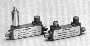
A coaxial systems reach higher frequencies, it then becomes critical to sample and level signals over broad instantaneous bandwidths. Two coaxial components from KRYTAR serve these purposes precisely: models 102040013 and 202040013 are a 13-dB directional coupler and directional detector, both operating from 2 to 40 GHz (Fig. 1).

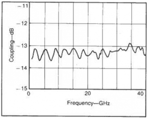
Model 102040013 is a 13-dB stripline directional coupler that uses a patented, nonuniform tapered line. The coupler is designed with offset coupled striplines used in a three- layer construction, with coupled lines etched on opposite sides of a thin center board that is in turn sandwiched between two dielectric boards of equal thickness. The design was synthesized with KRYTAR’s proprietary CAD program and, as a result, features flat RF performance not found in similar products. The coupler’s frequency sensitivity or coupling flatness is quite smooth at ±0.5 dB from 2 to 20 GHz, falling to a still respectable ±0.8 dB at 40 GHz. The frequency response of the coupler was measured with an ATE system built around a Wiltron 560A scalar network analyzer.
The coupler offers low insertion loss of 2.0 dB, in spite of its high operating frequencies. Directivity is 12 dB up to 20 GHz and 10 dB up to 40 GHz. The coupler has maximum VSWR of 2.0:1. Specifications are summarized in the table below.
| Specifications | Model 102040013 | Model 202040013 |
| Frequency Range | 2 to 40 GHz | 2 to 40 GHz |
| Nominal Coupling | 12 dB | – |
| Sensitivity | – | 20 𝜇V/ 𝜇W |
| Frequency Sensitivity | ||
| (2 to 20 GHz) | ±0.5dB | ±0.8dB |
| (2 to 40 GHz) | ±0.8dB | ±1.5dB |
| Directivity | ||
| (2 to 20 GHz) | 12 dB | 12 dB |
| (2 to 40 GHz) | 10 dB | 10 dB |
| Maximum VSWR | 2.0:1 | 2.0:1 |
| Maximum Insertion Loss | 2.0 dB | 2.0 dB |
Model 202040013 is a directional detector consisting of a low-VSWR, zero-bias Schottky detector mounted directly on the housing of the model 102040013 coupler. Elimination of the RF connector between the detector and the coupler saves space, minimizes frequency-response ripple normally caused by coupler/detector impedance mismatches, and improves the overall ruggedness of the design.

2. The coupling characteristics of the model 102040013 directional coupler are typically better than ±0.8 dB from 2 to 40 GHz.
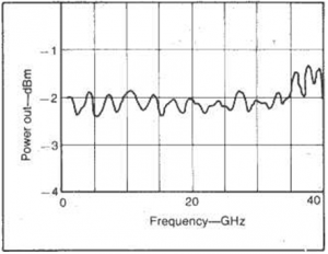
The detector circuitry is housed inside a hermetic coaxial detector module. This module is easily replaced in the field by unscrewing the detector output connector assembly (Fig. 3). The detector module is the same as used in the company’s series of 100-MHz-to-40-GHz zero-bias Schottky detectors. It was specifically designed to provide fast pulse response with an output capacitance of only 3 pF. This and a typical detector video impedance of 4 kohms give a typical unloaded output pulse rise time. of under 30 ns. The frequency response of the directional detector is ±0.8 dB from 2 to 20 GHz and ±1.5 dB from 2 to 40 GHz (Fig. 3). Frequency-response data were obtained by using a model 202040013 to externally level the output of a Wiltron model 6669A swept signal generator, and then monitoring the directional detector output with an ATE system incorporating a Hewlett-Packard HP 436A power meter.

Fig 3. The frequency response of the model 202040013 directional detector is typically better than ±1.5 dB or better from 2 to 40 GHz.
The 40-GHz directional coupler and detector are ideal for a wide variety of applications, including power monitoring in broadband EW systems and test setups and signal leveling in test systems. Both are available with either female 2.4-mm or female K connectors. The directional detector employs a female SM A, female BNC or SMC jack. The coupler housing is 1.75 X 0.65 X 0.40 in. (4.45 X 1.65 X 1.02 cm); the detector adds the 1.40-in. (3.56 cm) height of the detector module.

