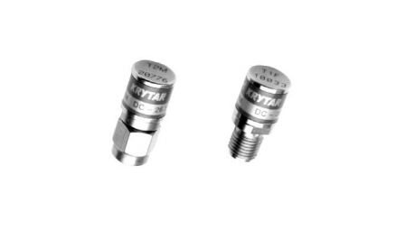
KRYTAR has designed an extremely rugged mechanical line of precision 50 Ohm Coaxial Terminations
that operate from DC to 50 GHz. The design offers reliable, long wear and excellent repeatability.
Some of these terminations have been in use at KRYTAR since 1988. Many have been used to make thousands
of measurements and are still within their specifications. See figure 1 for a listing of specifications
for each of the models currently offered.
| Frequency Range | Model | Maximum VSWR | Connectors | Dimensions |
| DC-20 GHz | T1M | 1.05 | 3.5mm M | 0.78” × 0.36” |
| DC-20 GHz | T1F | 1.07 | 3.5mm F | 0.73” × 0.35” |
| DC-26.5 GHz | T2M | 1.06 to 20 GHz 1.09 to 26.5 GHz |
3.5mm M | 0.78” x 0.36” |
| DC-26.5 GHz | T2F | 1.08 to 20 GHz 1.11 to 26.5 GHz |
3.5mm F | 0.73” x 0.36” |
| DC-40 GHz | T3M | 1.2 | 2.4mm M | 0.84” x 0.36” |
| DC-50GHz | T4M | 1.25 | 2.4 mm M | 0.84” x 0.36” |
Figure 1: Specifications for KRYTAR Terminations
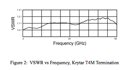
In addition to being extremely rugged, VSWR for these terminations is very low at the operating frequency band of each of the models listed. See Figure 2 for plot of VSWR vs Frequency for KRYTAR Model T4M which performs over the DC to 50 GHz frequency range. VSWR measurements are made with the Agilent 8510 network analyzer.
A termination fails for two reasons. The first is that its center contact may be insufficiently anchored. Some contacts are press-fitted into place. Others are glued or screwed on. The second kind of failure results from the way contact is made with the resistor. Tubular resistors are generally used and some rely on butting up against the center conductor.
The krytar terminations use a bead that is 0.34” long for the male and 0.19” long for the female. These dimensions provide solid axial support for center conductors. The bead and center conductor are captivated by an epoxy post going through the outer conductor bead and around a groove in the center conductor. Captivation is solid which typically requires a force of 15 to 20 pounds to break it loose.
Contact to the coaxial rod resistor is made with spring-loaded gold plated beryllium copper fingers. This allows for temperature expansion differences between the ceramic rod resistor and metal housing, resulting in a –65 to +125 degree C operating temperature range.
The termination design has been subjected to thermal shock testing per MIL-202, Method 107, Test Condition B. Five cycles of thermal shock throughout the –65 to +125 degree C temperature range was performed without any significant change in VSWR.
Each termination has the model and serial number permanently laser-inscribed on its metal cap which provides permanent traceability


