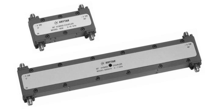
A broad line of 3 dB hybrids from KRYTAR features broad bandwidths together with tight amplitude
imbalances and phase imbalance specifications. ( See table 1 for detailed specifications of currently available
models).
| Frequency Range (GHz) |
Model | Amplitude Imbalance (dB) |
Phase Imbalance (Degrees) |
Isolation (dB Min) |
Maximum VSWR |
Insertion Loss (dB Max) |
| 0.5 – 7 | 3005070 | ± 0.4 | ± 5 | 19 | 1.3 | 1.3 |
| 2 – 8 | 3020080 | ± 0.35 | ± 3 | 19 | 1.25 | 0.65 |
| 1 – 12.4 | 1230 | ± 0.4 | ± 7 | 20 | 1.30 | 1.4 |
| 2 – 18 | 1830 | ± 0.4 | ± 7 | 17 | 1.35 | 1.4 |
| 1 – 18 | 1831 | ± 0.5 | ± 10 | 17 | 1.35 | 2.0 |
| 6 – 20 | 3060200 | ± 0.4 | ± 5 | 14 | 1.4 | 1.0 |
| 10 – 40 | 3100400 | ± 0.75 | ± 10 | 13 | 1.8 | 1.8 |
*Units with a tighter phase imbalance can be supplied Standard Connectors: SMA Female
90 degree hybrids are used in circuits requiring a balanced division of power into two transmission lines with 90 degree separation of phase. Applications include signal splitters, combiners, balanced mixers, image-rejection mixers, phase shifters, diplexers, switches and antenna feed networks.
The increasing use of broadband microwave systems has created a need for broadband 90 degree hybrids with tight output amplitude and phase tracking. All models use a three layer stripline construction. Coupled lines are etched on opposite sides of a thin coupler board sandwiched between two equal thickness dielectric boards. The tight 3 dB coupling is realized by using a non-uniform tapered line design synthesized with a CAD program developed at KRYTAR.
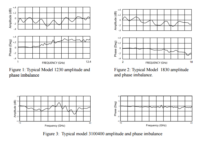
Typical amplitude and phase imbalance performance is shown in figure 3 for model 3100400 which covers 10 – 40 GHz. The identical 8.34 dB couplers are realized using a non-uniform tapered line design. These curves are of the 90 degree out port with respect to the zero degree out port. The data were taken with an automatic network analyzer. Figure 1 is phase and amplitude for model 1230 and Figure 2 is phase and amplitude for model 1830.


