KRYTAR Directional Couplers
0.5 TO 50 GHz Term Definitions Testing Typical Applications
1. Directional Coupler. Components that allow two microwave circuits to be combined into one integrated system in one direction with the two completely isolated from each other in the opposite direction. See Figure 1 above.
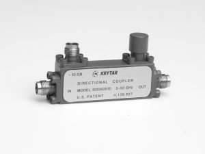
KRYTAR directional couplers have 4 ports. Port 1 is the input and port 2 is the output of the main line or thru line. This is the path of lowest insertion loss. Port 3 is the coupled power output. The fourth port is terminated with a precision microwave termination. Couplers usually have two separate circuits. The first is a mainline circuit and the second is a coupled circuit. When microwave power is applied to the mainline circuit (Ports 1 and 2) a certain amount of energy will be “coupled” to the coupled circuit (port 3). In general, the closer the circuits are together, the more power will be applied to the coupled circuit from the main line circuit.
2. Term Definition as applied to KRYTAR Directional Couplers.
- Frequency Range (GHz): The frequency bandwidth in GHz over which a particular model will perform while meeting all its specification limits. Currently available KRYTAR directional coupler designs operate over the frequency area beginning at 0.5 GHz up to 50 GHz. Current standard frequency bandwidths are listed on KRYTAR data sheets. Special frequency bandwidths can be designed. Higher frequencies (up to 65 GHz) are available with special engineering.
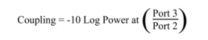
- Coupling (port 3) with respect to output (Port 2): This means that the power (dB) coupled from the mainline or thru line in KRYTAR directional couplers is with reference to the output (Port 2) KRYTAR directional couplers are generally very broad band (multi octaves of frequency). Many models are used in applications for internal leveling of power (signal generators for example) as well as for external leveling (See KRYTAR Application Idea #2 for an example of an external leveling loop for signal generators). For example, the power output from a broadband signal generator is usually the output (port 2) power from a directional coupler. If the power were referenced to the input, the coupled power from the input port would be used to level the power output of the signal generator. In that example, the power output from the signal generator would not be correct. The insertion loss of the mainline or thru line would need to be deducted to obtain the correct amount of power.Some standard values of coupling for KRYTAR directional couplers are 6 dB, 10 dB, 13 dB, 16 dB and 20 dB. Special coupling values are available upon request. Please note that the tolerance for setting the coupling value is specified from +/-0.3 dB to as much as +/- 1.0 dB. For example, if the nominal coupling value on a specific model is 10 dB and the tolerance is +/- 0.5 dB, the absolute coupling value could vary from unit to unit from 9.5 dB to 10.5 dB.Coupling in KRYTAR directional couplers is defined as:

- Frequency Sensitivity: Once the absolute coupling value has been determined (see 2B above), an additional variation in coupling value occurs – The absolute coupling value varies as a function of frequency. This is called frequency sensitivity. KRYTAR directional couplers have frequency sensitivity tolerances of +/-0.3 dB for narrow band models to +/- 1.2 dB for the broadest of the broad band models. The user should calculate absolute minimum and maximum coupling values to be expected using the following formula.Total coupling window= Frequency Sensitivity tolerance + Coupling ToleranceKRYTAR directional couplers are usually better than catalog specifications, both for sensitivity and coupling tolerances. However, catalog specifications should be used for calculations on new applications.
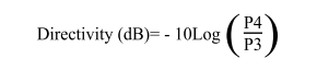
- Directivity: Port 4 (Isolated Port) is not completely isolated in KRYTAR directional couplers as there are no perfect terminations. A small amount of power will be present at the isolated port. If power out of port 4 (isolated port) is 20 dB below the power out of the coupled port, the directional coupler directivity is 20 dB. Directivity is defined as follows:

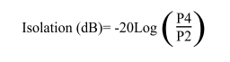
Where power is incident to port 2. P4 and P3 is the power at ports 4 and 3. - Isolation: Isolation is not normally specified on KRYTAR data sheets. KRYTAR feels that it is important to distinguish the difference of isolation and directivity. Isolation also measures the small amount of power present at port 4 (isolated port).
 P4 and P2 are power levels measured at Port 4 and Port 2 respectively.
Isolation (dB)= Coupling (dB) + Directivity (dB).Note that a 20 dB directional coupler with 15 dB directivity would have an isolation of 35 dB. KRYTAR data sheets specify directivity. - VSWR: (Voltage Standing Wave Ratio) or Return Loss: VSWR or Return Loss is caused by mismatches and discontinuities within the circuits of KRYTAR directional couplers. A mismatch on either port 1 (Input port) or port 4 (Terminated port) will reduce directivity by an amount equal to return loss (in dB) of the mismatch. This permits measurement of Return Loss. Note that measurement of accurate Return Loss requires very high directivity (typically 30 to 40 dB). KRYTAR can select directivity on some models over narrow frequency range to be in the 20 to 25 dB area. This would be sufficient for some “go”, “no go” applications. For example: A directional coupler with a directivity of 25 dB and a return loss of 21 dB on Port 1 (Input Port) permits measurement of a device under test connected to Port 1 with an accuracy of +/- 0.8 dB. Better accuracy may be achieved with higher directivity. The equation for calculating return loss is shown below. A graph showing calculations for this equation are displayed in figure 2 below.

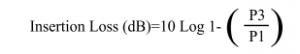
- Insertion Loss: KRYTAR Insertion loss includes coupled power. In a coupler with no dissipation, the thru or main line loss (Port 1 to Port 2) caused by the power coupled to Port 3 (Coupled Port) is:
 Dissipation in the circuit will raise the insertion loss by the power dissipation in dB. Insertion loss vs coupling (dB) for a coupler with no dissipation is shown in figure 3 below.

 P4 and P2 are power levels measured at Port 4 and Port 2 respectively.
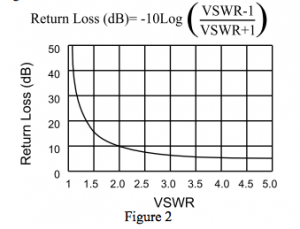
 Dissipation in the circuit will raise the insertion loss by the power dissipation in dB. Insertion loss vs coupling (dB) for a coupler with no dissipation is shown in figure 3 below.
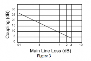
1. Power Leveling: Power leveling is the ability to hold power output constant as a function of frequency. Broad band signal generators usually use Yig Oscillators (By varying dc current to a Yig Oscillator, the frequency of the oscillator will change as a function of the current input to the oscillator). To achieve very broad band frequency and power output, one or more Yig Oscillators may be used. Power output from each of the Yig oscillators will vary as frequency is changed. A KRYTAR broadband directional coupler along with a KRYTAR broad band RF & Microwave Detector is used to sample the output power of the Yig Oscillator. The coupled output power from the Yig Oscillator is converted to a video (dc) voltage by a KRYTAR broad band detector. This voltage is supplied to an internal leveling amplifier to Level the output power from the Yig Oscillator. The power output from the signal generator is leveled by this method. The leveled power output from signal generators is usually port 2 of a directional coupler. This is an example why KRYTAR chooses to measure coupled power (Port 3) referenced to the Output (Port 2). KRYTAR directional couplers, detectors or directional detectors are also used in external leveling loops in many test setup (See KRYTAR application idea #2).
2. Frequency Measurement: Many times, a constant monitoring of frequency is necessary from the output of microwave transmitters, systems or special test setups. A directional coupler is connected to the output of the system or instrument. A small amount of power and frequency is coupled from the main line and connected to a frequency meter. This provides a constant measurement of frequency.
3. Power Monitor & Control: Power output from microwave transmitters may degrade as a function of time. A directional coupler may be used to couple a small amount of power from the main line. The power from the coupled port is then connected to a Power Meter where power can be constantly monitored. The power from the coupled port could be connected to a detector. The dc output voltage from the detector could be used in a feedback circuit to assure power output is constant – or – the voltage could be used to trigger shut down of the transmitter if the power is either to high or to low. The voltage could also be used to sound an alarm or trigger a computer to record data as long as the power was out of its operating window. If the transmitter is located in a remote location, the voltage could cause a telephone call to be made to a repair person to advise the transmitter was not performing to specifications.
4. Testing of Components or Systems: The directional coupler is used in many different testing applications where power or frequency needs to be monitored, leveled, alarmed or controlled.
A complete catalog, outline drawings and the latest applications ideas are available for all products manufactured by KRYTAR.