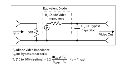
Risetime of a detector, in many applications, is very important. Risetime is a function of the value
of the Video Impedance, RF Bypass Capacitance and Load Resistance. See Figure 1, below, for an
Equivalent Circuit of KRYTAR Detectors.
Video Impedance is partially controlled by the type detector diode used to manufacture the detector.
For example, the Planar Doped Detector Video Impedance is normally between 0.8 to 3.0 K ohms. The
Zero Biased Schottky Detector is typically between 2.0 to 3.0 K ohms.
The Video Bypass Capacitance Value is chosen to set the low frequency performance of the detector.
For example, 3.0 pF is chosen for fastest risetime. This establishes the lowest operating frequency at
100 MHz. A value of 30 pF establishes the lowest operating frequency at 10 MHz. The higher value of
Video Bypass Capacitance causes a longer risetime. KRYTAR standard detectors have an output capacitance
of either 3.0 pF or 30 pF. The user must then decide whether low operating frequency or risetime is
more important for his application and choose the appropriate detector.
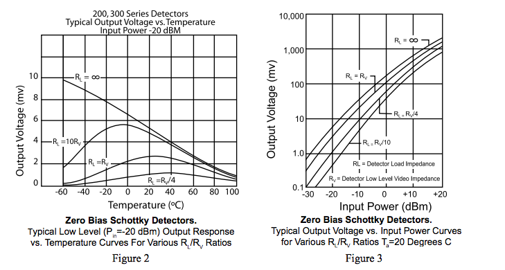
Load resistance seen by the detector also affects risetime. High Load Resistance will yield
longer risetime, but will result in higher Video (DC) output voltage. If risetime is the most important
parameter, the lowest Load Resistance capable of yielding an adequate Video (DC) output voltage from
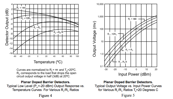
the detector should be chosen. The user should review temperature performance as shown in figures 2
and 4 to be sure that DC Output Voltage is adequate for the operating temperature range of the specific
application. If risetime is not important and Video (DC) Output Voltage is critical, then a high Load
Resistance should be chosen. See figures 3 and 5 for typical output voltage vs. input power curves for
various RL/RV, ratios for both the Planar Doped Barrier and Zero Bias Schottky Detectors.
Planar Doped Barrier vs. Zero Bias Schottky Detectors