Equipment Required
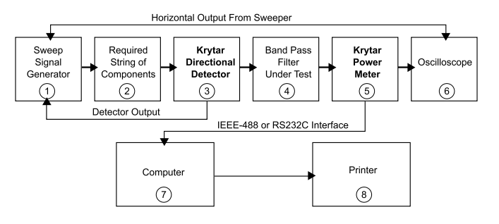
- Sweep Signal Generator: Select a Sweep Signal Generator capable of a frequency bandwidth that is much greater than the operating frequency of the Filter Under Test.
- Required “String of Components” such as isolator, cable assemblies, etc.
- KRYTAR Directional Detector
- Filter Under Test: The above test setup will also measure all types of filters (Band Pass, High Pass, Low Pass, Band Reject). Other Passive Devices or Components may also be measured (i.e. Attenuators, Step Attenuators, Pads. Insertion loss of Cable Assemblies, etc.).
- KRYTAR Power Meter with Power Sensor: Choose the Power Sensor with a frequency bandwidth much greater than the Filter Under Test. KRYTAR Power Sensors are available with bandwidths from 100 KHz to 40 GHz.
- Oscilloscope, The Oscilloscope should be capable of accepting a voltage input of -3.9 to +2 Volts DC (Equivalent to Power Measurement from the KRYTAR Power Meter of -39 dBm to+ 20 dBm}. The Oscilloscope should also be capable of accepting the Horizontal Output from the Sweep Signal Generator.
- Computer with IEEE-488 or RS232C Interface
- Printer
What Does it Measure
- C W and Swept Power from the output of the Band Pass Filter
- Minimum pass band insertion loss of the Band Pass Filter
- Frequency at which minimum insertion loss is measured.
- 3 dB bandwidth of the Band Pass Filter
- Both lower and upper stopband attenuation of the Band Pass Filter
- Frequency point at which “Return Band” or “Spurious Bands” occur as well as the attenuation value of the Band Pass Filter at these frequencies.
- Set the leveled output power from the sweep signal generator to its maximum (usually between +12 to +20 dBm). Maximum dynamic range for the KRYTAR Power Meter is -39 to +20 dBm. Note that if +20 dBm is supplied to the band-pass filter, stopband attenuation of 59 dB can be measured.
- Many test setups have one or more components (Isolators, connectors, cable assemblies, etc.) connected between the output connector of the sweep signal generator and the Unit Under Test. These components introduce insertion loss.
- Remember, the power output from the sweep signal generator is leveled at the output connector. Any components added between the output connector of the sweep signal generator and the Unit Under Test will attenuate the power to the unit under test. The output from the “Test String of Components” Is connected to the input of KRYTAR Directional Detector. The output from the KRYTAR Directional Detector is connected to the Band Pass Filter being tested. The DC voltage from the Directional Detector is connected to the “External Leveling” connector of the sweep signal generator. This will level the power at the output of the KRYTAR Directional Detector (Note that the detected output is referenced to the output of the directional detector}. If the sweep signal generator is unable to furnish adequate leveled output power to the band pass filter, an amplifier will need to be added to the test string of components. A KRYTAR Power Meter way be connected to the output connector of the Directional Detector to assure adequate power is furnished to the Band Pass Filter. The Power Meter is then removed and the Band Pass Filter is connected to the output connector of the Directional Detector.
- The output from the Band Pass Filter is connected to the KRYTAR Power Meter. CW Power is measured and displayed on the Power Meter.
- The KRYTAR Power Meter supplies a DC Voltage of -3.9 Volts to +2 Volts which is equivalent to -39 to +20 dBm of power.
- The DC voltage from the KRYTAR Power Meter is connected to an Oscilloscope. The DC Voltage is shown on the Oscilloscope as a calibrated attenuation (0 to -59 dB). The horizontal Output connector from the sweep signal generator is connected to the horizontal input of the oscilloscope. The oscilloscope trace will then be calibrated to show frequency as generated by the sweep signal generator. The oscilloscope will then display attenuation versus frequency of the Band Pass Filter being tested.
- The KRYTAR Power Meter may be ordered with an IEEE-488 or RS232C interface. All readings firm the Power Meter may be stored on a computer. A report may be generated using a spread sheet program like Microsoft Excel or equivalent.
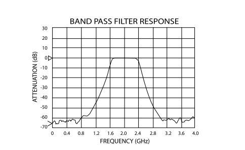
See the attenuation curve (above) of a typical Band Pass Filter measured using this test setup. This test setup may be used to measure other passive devices such a Band Reject, High Pass, Low Pass and Stop Band Filters as well as fixed attenuators, pads, step attenuators, insertion loss of cable assemblies, etc.