Equipment Required
- Microwave Sweep Generator with minimum sweep bandwidth of 1.0- to 26.5 GHz
- KRYTAR Directional Coupler, Model 2620 with bandwidth of 1.0 to 26.5 GHz
- KRYTAR Model 9000B Power Meter with 9530A Power Sensor and IEEE-488 Interface Option
- Amplifier Under Test. Bandwidth may be anywhere between 1.0 to 26.5 GHz
- KRYTAR Model 9000B Power Meter with 9530A Power Sensor and IEEE-488 Interface Option
- Dual Trace X-Y Oscilloscope with horizontal sweep input
- Computer that will accept IEEE-488 measurements from each of two power meters
- Printer
What Does it Measure?
- 1. CW and Swept Power Input to the Amplifier Under Test. Accurate CW Power Input may be
read directly from the digital display of the Power Meter. Swept Power Input is displayed on the
Oscilloscope. - CW and Swept Power Output from the Amplifier Under Test. Accurate CW Power Output may be
read directly from the digital display of the Power Meter. Swept Power Output is displayed on the
Oscilloscope. - Gain may be calculated (Power Output minus Power Input).
- Swept gain flatness (Power Output Curve) is displayed on the Oscilloscope.
- CW Output Power at 1 dB can be derived (Point where CW Output Power is 1 dB less than CW
Input Power as Input Power is increased). - CW Saturated Output Power can be derived (The point at which the CW Output Power does not
increase when Input Power continues to be increased). - P1dB and Psat may also be read directly from the oscilloscope by comparing swept Output Power
versus swept Input Power.
Microwave & RF Amplifier; Power Input VS. Power Output
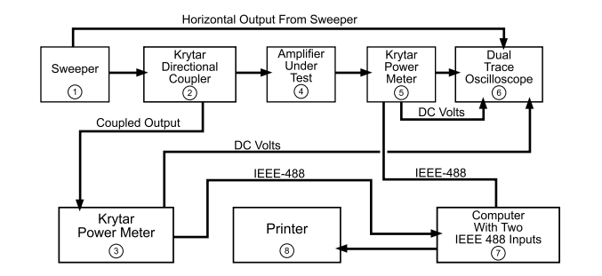
• The sweeper generates a microwave frequency of 1.0 to 26.5 GHz with a leveled power output of up to +10 dBm. The power goes through the coupler to the Amplifier Under Test. 20 dB of the power is coupled to a KRYTAR Power Meter. The meter can read a CW Power Range of -30 to + 20 dBm and is usable to -39 dBm. See KRYTAR Data Sheet (located on KRYTAR Website www.Krytar.com) for full specifications. The KRYTAR Power Meter is able to measure swept power at a 100 ms sweep rate. A 200 ms sweep rate is suggested for this measurement.
• The Power Meter has a DC voltage output of -2 to +3 Volts which is equivalent to an input power of -30 dBm to +20 dBm. This output is connected to the first trace of an X-Y dual trace Oscilloscope. The power may also be sent from the Power Meter thru an IEEE-488 interface or RS232C Serial port to a computer. The horizontal sweep output from the sweeper is connected to the oscilloscope. The calibrated swept frequency from the sweeper is displayed on the oscilloscope. This allows measurement of Amplifier Power Input to the Amplifier Under Test to be displayed (as a function of frequency) on the oscilloscope. The CW power may be read directly from the Power Meter Display.
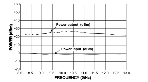
• The Amplifier Under Test receives power from the sweeper. The output power from the Amplifier goes directly into a KRYTAR Power Meter. Power output of -30dBm to +20 dBm measured by the meter is also converted to -3 to +2 Volts DC and connected to the second trace of the Oscilloscope. Swept power output (as a function of frequency) from the Amplifier Under Test may then be read directly from the oscilloscope. The CW Power Output may be read directly from the Power Meter. If the power output from the Amplifier Under Test is greater than +20 dBm, a Pad or Step Attenuator may be used to reduce maximum power from the amplifier to less than + 20 dBm. The output power may also be routed from the Power Meter to the input of a computer via an IEEE-488 interface or an RS-232C Serial Port.
• Any anomalies of the swept power input or power output over the frequency of interest will be displayed on the oscilloscope. The sweeper may then be set on the exact frequency of the anomaly and an accurate CW output power may be read directly from the digital display of the Power Meter at that frequency.


