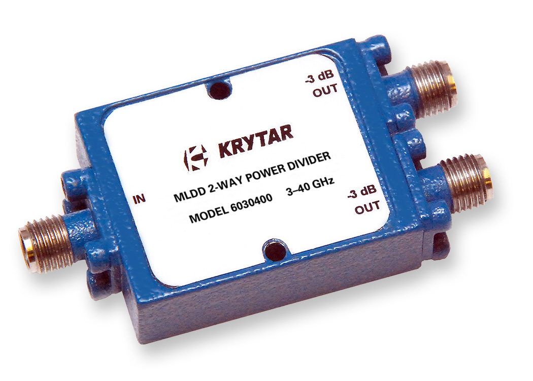
2-Way Power Dividers 6030400
SPECIFICATIONS
Model Number
Freq. Min. (GHz)
Freq. Max. (GHz)
FEATURES
3.0 – 40.0 GHz (S thru Ka-Bands) Frequency Operation
Isolation: >14 dB
Insertion Loss: <2.1 dB
Amplitude Tracking: ±0.5 dB
2.4-mm Female Connectors
Custom Designs Available
Product Description
KRYTAR MLDD 2-way power dividers lend themselves to emerging wireless ultra-broadband designs and many test and measurement applications. KRYTAR has used its proprietary design to produce a wide assortment of matched-line directional dividers (MLDD) with ultra-high performance over a broadband frequency range. KRYTAR MLDD 2-way power dividers are a new class of patented directional devices.
KRYTAR’s MLDD 2-way power divider, Model 6030400, offers high performance over the ultra-broadband frequency range of 3.0 to 40.0 GHz (S thru Ka-Bands) in a compact, lightweight package.
KRYTAR’s technological advances provide excellent operating performance of this new 2-way unit. Model 6030400 covers the full frequency range from 3.0 to 40.0 GHz with >14 dB Isolation and ±0.5 dB of maximum Amplitude Tracking, with maximum Phase Tracking is ±8 degrees. The 2-way divider exhibits Insertion Loss of <2.1 dB across the full frequency range. Maximum Input VSWR is 1.9 and Maximum Output VSWR is 2.1. Input power rating is 10 watts with 2:1 load VSWRs. Units with tighter amplitude and Phase Tracking specifications can be supplied. Contact the factory with your requirements.
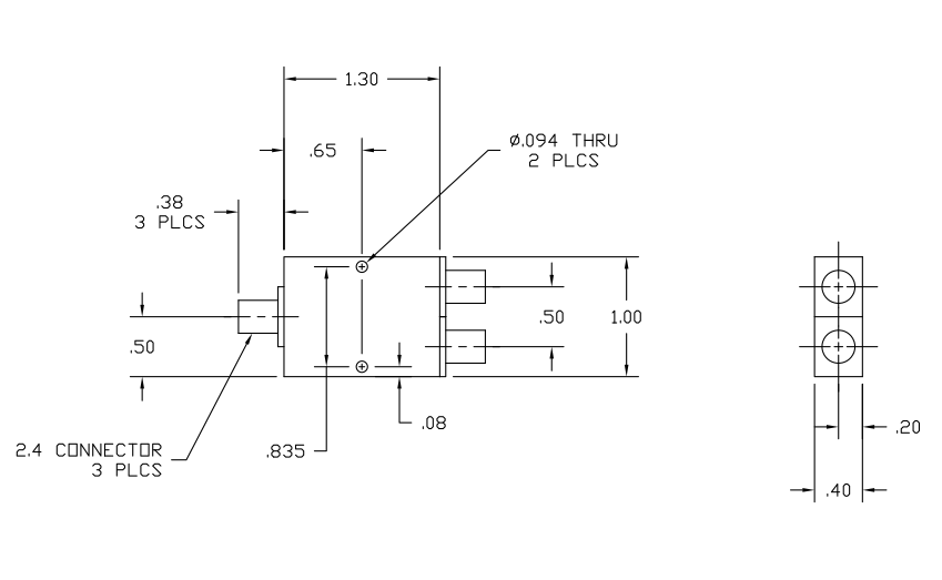
The power divider is a compact package measuring just 1.30 inches (L) x 1.00 inches (W) x 0.40 inches (H), weighs only 1.1-ounces, and comes with standard 2.4-mm coaxial female connectors.
KRYTAR’s new power divider offers the widest frequency coverage in a single package on the market and provides superior performance. Targeting broadband electronic warfare (EW) systems and complex switch-matrix applications, for example, KRYTAR has used its proprietary design to produce a wide assortment of matched-line directional dividers (MLDD) with ultra-high performance over a broadband frequency range. The directional coupler can also be manufactured to meet ridged military specifications.
KRYTAR also offers complete engineering services for custom designs that meet or exceed critical performance and/or packaging specifications.
Common Definitions
| Microwave Frequency Bands | |
| Band Designation | Frequency Range (GHz) |
| UHF | 300 MHz – 1.0 GHz |
| L | 1.0 – 2.0 |
| S | 2.0 – 4.0 |
| C | 4.0 – 8.0 |
| X | 8.0 – 12.0 |
| DBS | 12.2 – 12.7 |
| Ku | 12.0 – 18.0 |
| K | 18.0 – 26.5 |
| Ka | 26.5 – 40.0 |
| Q | 30.0 – 50.0 |
| U | 40.0 – 60.0 |
| V | 50.0 – 75.0 |
Power Dividers: A power divider splits an input signal into two or more outputs that are usually, but not always, equal in amplitude and phase. Regardless of its type, the goal of every power divider is to have the greatest port-to-port isolation, lowest insertion loss and voltage standing wave ratio (VSWR), and least amplitude and phase imbalance over the entire frequency range of the device.
Insertion Loss is the net unrecoverable power in dB dissipated within the circuit at any frequency within the specified range.
VSWR is defined as the ratio of the maximum voltage to the minimum voltage in standing wave pattern along the length of a transmission line structure. It varies from 1 to (plus) infinity and is always positive.
Amplitude and Phase Tracking are the ratio of one output to the other in dB or degrees respectively.
Frequency Sensitivity is the amount of frequency change in the carrier frequency per unit amplitude change in the message signal.
Wilkinson Power Divider: Ernest Wilkinson, “N-way hybrid power divider,” was published in “Institute of Radio Engineers (IRE, now the IEEE) Transactions on Microwave Theory and Techniques” in 1960. The Wilkinson power divider was created in part as a solution to the problems of matching and isolation that are inherent in a typical T-junction divider, in which a large amount of the power reflected from port 2 enters port 3 and thus provides little isolation. The Wilkinson power divider employs quarter-wavelength transformers to divide the input signal. This design achievement made the reactive Wilkinson power divider a staple of RF and microwave design.


