Equipment Required
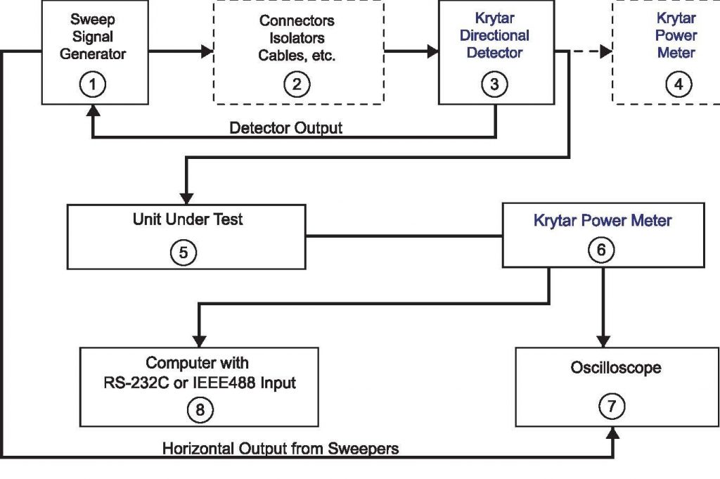
(1) Sweep Signal Generator capable of supplying leveled output power. The Sweep Signal Generator must have an external leveling loop capability and a frequency bandwidth required for testing Unit Under Test
(2)Amplifier, Connectors, Isolators, Cables, or Other Components Used in a Typical Test Setup
(3) KRYTAR Directional Detector selected for proper frequency bandwidth for testing Unit Under Test.
(4) KRYTAR Power Meter Selected for Frequency Bandwidth for testing Unit Under Test
(5) Unit Under Test
(6) KRYTAR Power Meter Selected for Frequency Bandwidth for testing Unit Under Test
(7) Oscilloscope for Displaying Output of Unit Under Test
(8) Computer Capable of Accepting Data via RS232C or IEEE-488.
How It Works
The power from the signal generator is leveled at the output connector of the signal generator. In general, additional components as used between the output connector of the Sweep Signal Generator and the Unit Under Test (i.e. Cable Assemblies, Isolators, etc..). These components Introduce Insertion loss. The power at the end of the test string of these components needs to be measured to assure that the proper amount of power is being supplied to the Unit Under Test. If the power is not of the correct value, the Sweep Signal Generator output power must be adjusted until the correct power is obtained. If the insertion loss (caused by the test string of components) is great enough, the Sweep Signal Generator may not be able to provide adequate leveled power required to test the Unit Under Test. An amplifier may be needed to boost the power to an adequate level.
1. The output connector of the Sweep Signal Generator is connected to the input connector of the string of test components.
2. The output of the test string of components is connected to the input connector of the thru port of a KRYTAR Directional Detector. The output port of the thru line of the directional detector is connected to a KRYTAR Power Meter. The output power from the Sweep Signal Generator is adjusted until the correct amount of power is read on the KRYTAR Power Meter Display for testing the Unit Under Test. The test setup is now calibrated to begin testing. Remove the KRYTAR Power Meter and connect the output connector from the thru port of the KRYTAR Directional Detector to the Unit Under Test.
3. Connect the DC Output Voltage from the Detector (an integral part of the Directional Detector) to the External Leveling Connector located on the Sweep Signal Generator. The Sweep Signal Generator Leveling Loop will level power at the output connector of the directional detector..
4. Connect the output of the Unit Under Test to the KRYTAR Power Meter (the same Power Meter used to calibrate the power at the output connector of the Directional Detector may be used).
5. The KRYTAR Power Meter provides a DC Voltage of-3 Volts DC to +2 Volts DC which is equivalent to -30 dBm to +20 dBm This voltage is connected to an Oscilloscope. The Oscilloscope can be calibrated to display the swept output from the Unit Under Test as a function of frequency.
6. The KRYTAR Power Meter (furnished with optional RS232C or IEEE-488 interface) may then be connected to a Computer that is capable of accepting RS232C or IEEE-088 data. Data can be stored by the computer. Using Excel or other spreadsheet programs, complete test reports can be made.
HINT: KRYTAR components and Power Meters are available with various frequency bandwidths up to 40 GHz. Choose a frequency bandwidth that will cover all your needs. Then, you may use the same test set for all measurements.


