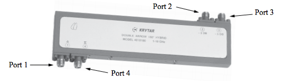
When a signal is applied to port 1, the output signal will appear on ports 2 and 3. Ports 2 and 3 are 180 degrees out of phase with each other. When a signal is applied to port 4, the output signal will appear on ports 2 and port 3. Ports 2 and 3 are in phase with each other.
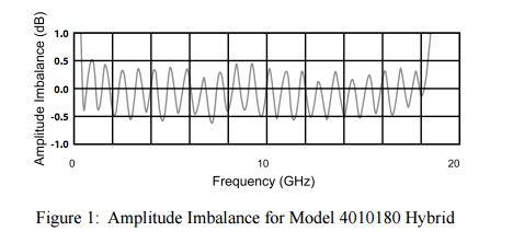
Amplitude Imbalance Measurement
The specification for Amplitude Imbalance for Model 4010180 is ±0.6 dB. Krytar measures amplitude imbalance from output port 3 to port 2 (0.0 dB reference) with a vector analyzer. (See Figure 1). Note maximum deviation from the zero reference is approximately -0.6 db which appears at approximately 7.5 GHz. Because there is no corresponding positive peak at the specific frequency of 7.5 GHz, the allowable total deviation at that specific frequency would then be 1.2 dB. The definition for amplitude imbalance of Krytar Model 4010180 3 dB 180 degree hybrid is: 1.2 dB maximum from the 0.0 dB reference at any specific frequency point within the frequency band of 1.0 to 18.0 GHz.
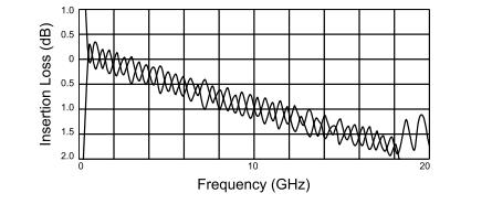
Insertion Loss Measurement
The specification for Insertion Loss for Model 4010180 is 2.9 dB maximum. The insertion loss is measured from Port 1 to Port 2 and for Port 1 to Port 3 using a vector analyzer (see figure 2). Insertion loss from Port 2 is superimposed on Insertion loss of Port 3. Note that maximum insertion loss over the entire frequency band is approximately 1.83 dB.
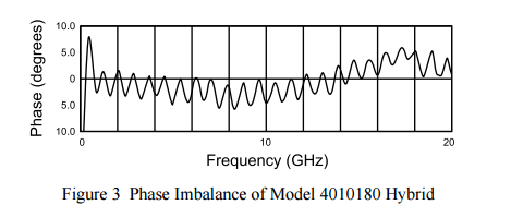
Phase Imbalance Measurement
The specification for phase imbalance for Model 4010180 is ±12 degrees. The measurement is made using a Vector Network Analyzer. Phase imbalance is defined as the difference between phase of port 3 to port 2 over the operating frequency bandwidth of the Hybrid. Note that phase imbalance is approximately 12 degrees (See Figure 3).
Isolation
Isolation (dB) is measured between port 3 and port 2.
VSWR
Voltage Standing Wave Ratio is the mismatch that occurs when measuring Port 2 or port 3 into an
impedance of 50 ohms.
Coupling
Coupling is the power in dB coupled from the main line (Port 1) to Port 2 and from Port 1 to Port 3. For 3 dB Hybrids, the coupled power would be 3 db less the insertion loss of the main line (Port 1). The power would be split equally between ports 2 and port 3.